RZS control boxes from Metalchem-Warszawa S.A. they are used to automatically control the operation of pumping stations for power pumps from 1.1 ÷ 22 kW of own production or any power for pumps from other manufacturers. Control boxes are available in a relay-contactor version and based on a microprocessor controller.
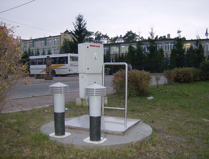
Our control boxes have a “Declaration of Conformity” with directives and harmonized standards in force in the European Union. The design of the control boxes provides IP-65 protection when closed and IP-21 when the enclosure door is open. The control boxe is made of non-flammable polyester material. As a standard, the control boxe is mounted on a plastic pedestal, which is mounted on a previously poured concrete pedestal located next to the pumping station. In the case of a considerable distance from the pumping tank, a cable connector should be used to extend the pump and signal sirens. Power supply should be made in the TN-S network system.
In our control box we featured:
- work system with one pump,
- work system with two pumps,
- work system with three pumps,
- special work systems, according to customer requirements.
The control systems start the electric motors of pumps (made by Metalchem):
- direct for engine power from 1.1 kW to 4 kW,
- intermediate (star-delta) for engine power from 4 kW to 22kW,
- based on Soft-Start systems for engine power from 1- 22 kW,
- any other for pumps from other manufacturers.
Types of pumping station control:
Sewage pumping station control
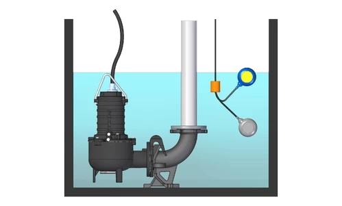
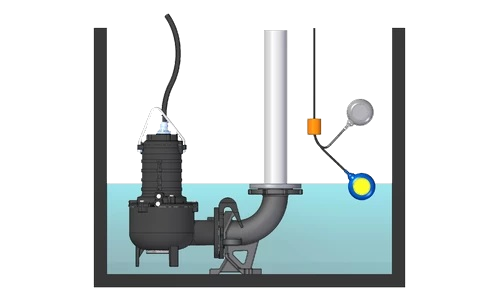
A typical control of a sewage pumping station is realized through 4 levels:
- Level ALARM – the pumping station is exceeded, pump II switches on, acoustic and optical signaling and in the case of monitoring, a signal is sent to the user,
- Level MAX – level of pump I activation at normal pumping station operation,
- Level MIN – level of pump deactivation, equivalent to emptying the sewage pumping station,
- Level SUCHOBIEG – protection of pumps against dry running and engine overheating – achieved by manual control.
Rainwater pumping station control
A typical control of a rainwater pumping station is realized through 5 levels:
- Level ALARM – the pumping station is exceeded, pump II switches on, acoustic and optical signaling and in the case of monitoring, a signal is sent to the user,
- Level Pompa II – level of pump II activation at normal pumping station operation and increasing inflow,
- Level Pompa I – level of pump I activation at normal pumping station operation,
- Level MIN – level of pump deactivation, equivalent to emptying the sewage pumping station,
- Level SUCHOBIEG – protection of pumps against dry running and engine overheating – achieved by manual control.
Household pumping station control
A typical control of a home pumping station is realized through 3 levels:
(When using control boxes)
- Level ALARM – the pumping station is exceeded, pump II switches on, acoustic and optical signaling and in the case of monitoring, a signal is sent to the user,
- Level MAX – level of pump I activation at normal pumping station operation,
- Level MIN – level of pump deactivation, equivalent to emptying the sewage pumping station.
ATTENTION!
Even the best control of a pumping station cannot replace the periodic operation of a pumping station, its inspection, cleaning the tank or checking the condition of pumps! The correct control of the pumping station is invaluable in diagnostics and planning of maintenance operations. Therefore, the most important for us is the correct analysis of your needs and the selection of the appropriate control algorithm.
Analog and with microprocessors control boxes
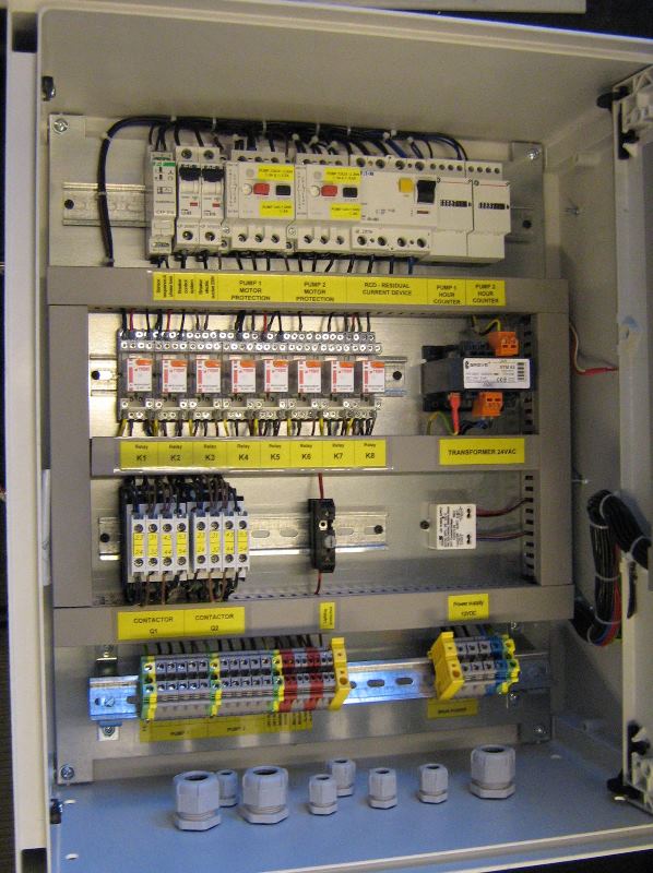
Analog control boxes – relays-contactors
The relay-contactor control boxes are the simplest systems implementing the control of the pumping station, their advantage is the simplicity of construction and quick repair. However, this is associated with a limited number of control functions compared to control boxes containing microprocessor controllers.
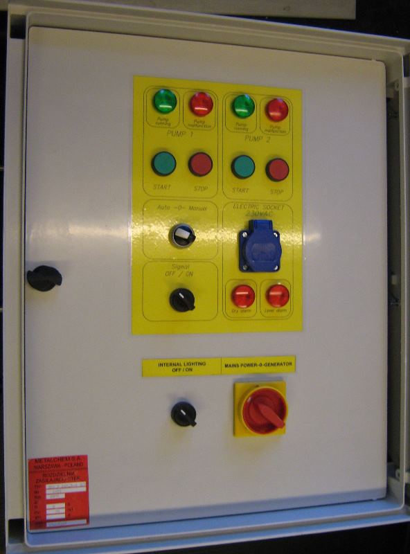
Typical equipment analog control box:
- Switch Main-0-Additional. 32A plug.
- Electric shock protection – residual current circuit breaker.
- Overload protection for each pump.
- Sensor of phase decay and asymmetry.
- Circuit breakers for the control system.
- 230VAC / 10A socket.
- Electromechanical counters of pump operating hours.
- Electromagnetic relays.
- Time relays for indirect start pumps.
- Blocking of pump activation in case of opening of the circuit (1-2) protecting the pump (circuit is opened in case of damp or motor overload).
- Optical-acoustic signaling device.
- Buttons STOP – START.
- Work selection mode AUTO – 0 – MANUAL.
- Control lights.
Additional equipment:
- Repair outlet 3x400VAC / 16A or 32A.
- Socket 24VAC/6A.
- Voltmeter.
- Ammeters.
- Leading individual potential-free signals to a strip.
- Heater with thermostat.
- Surge arrestor class T2 (C) – four poles.
- Twilight automaton.
- MRT-GSM communication modem.
- Individual according to customer specifications.
Control boxes with microprocessor
Control boxes with microprocessor controllers are currently the widest group of control boxes that control the pumping station, regardless of its type. Controllers available on the market can be divided into general purpose controllers and controllers designed only for pumping stations. Most of our control boxes are built based on the SP62 controller and its earlier versions SP12; SP22; SP32; SP42 and SP52. The SP62 controller is our latest controller and is characterized by a color touch liquid crystal display, a built-in SIM card slot and an RS485 connector. At the customer’s request, we can make control boxes with other freely programmable controllers available on the market as; Eaton, Siemens, Unitronics, etc ..
Basic functions of the control box:
- Pump control Automatic or Manual.
- Alternating pump operation.
- Offset of pump activation after power failure and after exceeding the alarm level.
- Switching the lead pump to the other one if it would fail.
- In the case of continuous operation, change of pump operation every 20 minutes.
- In manual mode it is possible to pump the liquid to dry running level.
- Arrears function (short work with long wait and low flow).
- Possibility of blocking the simultaneous operation of two pumps after exceeding the alarm level.

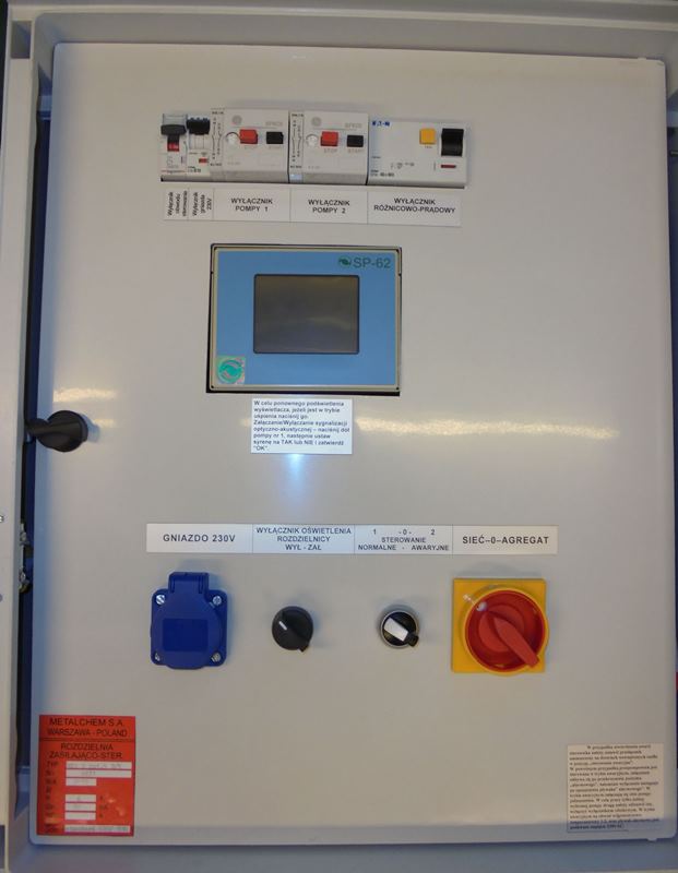
Standard equipment of switchgears based on a microprocessor controller:
- Switch Main-0-Additional. 32A plug.
- Microprocessor controller with built-in GSM / GPRS modem and color touch screen (SP62).
- Overload protection for each pump.
- Sensor of phase decay and asymmetry.
- Socket 230VAC/10A.
- Counters of working hours and number of starts for each pump.
- Blocking of pump activation in case of opening of the circuit (1-2) protecting the pump (circuit is opened in case of damp or motor overload).
- Optical-acoustic signaling device.
- Emergency control switch (bypassing the controller).
- Automatic or Manual Control (Start / Stop).
- Surge arrestor class T2 (C) – four poles.
Additional equipment:
- Repair outlet 3x400VAC / 16A or 32A.
- Current transducer (current measurement of pumps in one phase),
- Socket 24VAC/6A.
- Voltmeter.
- Ammeter.
- Leading individual potential-free signals to a strip.
- Heater with thermostat.
- Surge arrestor class T1 + T2 (B + C) – four poles.
- Twilight automaton.
- Individual according to customer specifications.
SP62 microcontroller and its possibilities
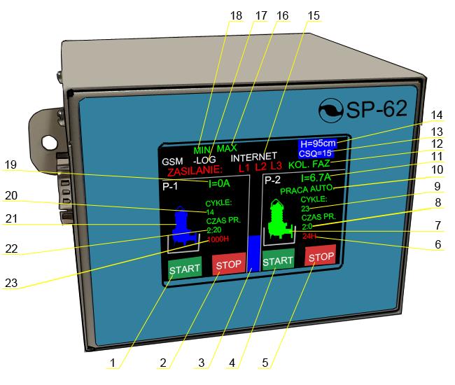
- Pump Start 1
- Pump Stop 1
- Level Bar
- Pump Start 2
- Pump Stop 2
- Daily pump operation counter 2
- Pump icon 2
- Pump time counter 2
- Pump start counter 2
- Pump operation status 2
- Pump curent 2
- Power supply status 3x400V
- GSM signal strength
- Waste water level in the tank
- Internet login status
- Float max condition
- GSM login status
- Float min condition
- Pump current 1
- Pump start counter 1
- Pump icon 1
- Pump time counter 1
- Repair cycle counter p1
The colors of the pump icons mean:
- blue/black – efficient pump, not working
- green – the pump works in automatic mode
- yellow– the pump works in manual mode
- red – pump in a state of failure
- white – pump stopped
SP-62 is a controller designed specifically to operate two-pump pumping stations.
Thanks to this, the number of elements of the power supply and control switchgear is limited to a minimum. The SP-62 controller contains all possible algorithms for controlling a pumping station with two pumps. It is equipped with an operator’s touch panel on which the current status of the pumping station is depicted:
- Status of float level switches.
- Current level of sewage in digital and analogue form (bargraph).
- GSM network login status (GPRS, INTERNET)
- Signal level of the CSQ cellular network in the range of 0-31.
- Pump current (I).
- Number of pump starts (CYCLES).
- Pump running time counter (PR TIME).
Controller configuration is made using 10 screens equipped with a numeric keypad.
Operating modes of the SP-62 controller
- Manual control using buttons on the START, STOP screen, icon pump kyellow.
- Automatic control via level control devices (floats, hydrostatic probe and others), icon pump green.
- Control of pumps with direct start.
- Pump control with indirect start with star-delta switching.
- Level control using four floats.
- Level control using five floats (rainwater pumping station).
- Level control with a hydrostatic probe and two floats.
- Control with blockade of simultaneous operation of pumps (limitation of pumping power).
- Control using a hydrostatic probe and floats.
- Control system with control of sewage retention time in low-flow pumping stations.
- Control limited to 20 minutes of continuous pump operation time to avoid overloading.
- Control with cyclical simultaneous activation of both pumps during operation below the alarm level in order to increase the expenditure for cleaning the pipeline from deposits.
The SP-62 controller controls:
- The presence of all phases L1, L2, L3, inscriptions in color green, malfunctions inscriptions in color red.
- Phase-to-phase voltages.
- Phase shift values, PHASE COLOR green indicates the correct phase sequence, red indicates the wrong phase sequence.
- Thermal sensor circuit.
- Humidity sensor circuit.
- Motor circuit breaker.
The SP-62 controller is equipped with a GSM modem and can monitor the operation of the pumping station:
- On the website, sending data directly to a web server.
- In a local computer equipped with a SCADA program with the possibility of full control using GPRS packet data transmission.
- In a mobile phone using a smartphone application with full control.
Description of the SP-62 controller operation
- Automatic alternating pump control depending on the level of wastewater in the tank.
- In case of failure of one pump, the control automatically switches to a functional pump.
- After detecting an open circuit (1,2) protecting one of the pumps, the controller will display the icon of the given pump red. To restore the pump to work, remove the cause of the failure and clear the alarm in the controller with the “START” button.
- Switching contactors with a time delay during automatic or manual operation enables the controller to operate in a direct start system and in a system with star-delta switching.
- Timer functions:
- Counting the P1 pump running time.
- Counting pump operation time P2.
- Counting the P1 pump operation time in the 1000 hour repair cycle.
- Counting the P2 pump operation time in the 1000 hour repair cycle.
- Adding up the P1 pump running time over 24 hours to determine the time overload of the pump.
- Adding up the P2 pump running time over 24 hours to determine the time overload of the pump.
- Counting the controller working time.
- Counting the number of P1 pump starts.
- Counting the number of pump starts P2.
- Alarm signaling:
- Audible for 1 minute.
- Light going on until the failure disappears.
- Activation or deactivation of the sounder is done by means of the pump 1 configuration screen, which is activated by pressing the lower part of the pump 1 icon, the active field is marked with a white frame.
- The optical signaling device is switched on or off by means of the pump 2 configuration screen, which is activated by pressing the lower part of the pump 2 icon, the active field is marked with a white frame.
- If the seizure function is set in the controller menu, and the cabinet is adapted to monitor the so-called burglary, then after opening the cabinet or hatch, the optical-acoustic signaling will be activated. burglary. Turning off the light and sound signaling device is done by pressing the lower part of the pump 2 icon (if the screen is in sleep mode, it should be activated). The alarm will be reactivated after closing the cabinet / hatch (15sec.)
- The configuration of pump 2 is started by pressing the lower part of the pump 2 icon, the active field is marked with a white frame. Setting the control levels is achieved thanks to the screen activated by pressing the inscription area H = (level value) cm in the upper right corner. Procedure: delete the current value (<=), enter a new one from the keyboard and confirm with OK.
Note: The minimum level must be at least 10 cm higher than the probe suspension.
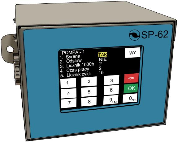
Pump 1 configuration settings screen:
1. The setting currently being changed is marked with a background yellow.
2. Button red is used to delete the numeric settings.
3. Button green i used to confirme settings.
4. Button „WY” is used for return to main screen.

Level settings screen.
The “KON1” button is used for advanced settings protected by a pin.
The change of the level value should be preceded by the deletion of the current value red button, and then enter the new value and confirm with the button green.
Attention!
The minimum level value must be at least 10 cm higher than the probe suspension value.
Emergency control
In the event of a controller failure, the switch located on the inside door of the cabinet should be set to the “emergency control” position.
In the above case, the pumping station is controlled in emergency mode, switching on takes place after exceeding the “alarm” level – raising the float, while the pumps are switched off after leaving this float.
In emergency mode, both pumps are switched on simultaneously. In order to work only one selected pump, the other should be put down, i.e. turned off with the motor switch.
ATTENTION: In emergency mode, the humidity and temperature circuit 1-2 and the alarm float are supplied with 230VAC.
A damaged controller should be removed from the cabinet and sent to the service center to remove the fault.
After removing the controller fault and installing it in the cabinet, set the switch located on the internal door of the switchgear in pos. “Normal control”.
Possible events and their elimination:
► Motor circuit breaker – The cause of tripping of the motor protection switch is motor overload caused by clogged pump or mechanical blockage of the pump rotor. Overloading the motor causes the motor to consume more current than the nominal one set on the motor breaker. Take out the pump and clean the impeller (rags, cords etc.). Another cause of overloading may be pumping liquids with a density and viscosity greater than the permissible.
After activation of the motor switch or both, the optical-acoustic signaling is switched on and information on the controller is displayed. If the pump impeller is clean and the motor switch is still activated, check the motor windings and check the continuity of the humidity-temperature circuit 1-2.
► Moisture and temperature circuit 1-2 –The reason for opening circuit 1-2 may be water entering the engine compartment, or overheating. If the failure persists, the pump should be repaired. Each opening of circuit 1-2 of the first or second pump causes an optical-acoustic signaling device and information on the controller will be displayed.
► Dry running – One of the reasons for the dry running level may be the pumping of the liquid below the minimum level / level switching off the pump, or suspension of the level switch. It is necessary to check the liquid level in the tank and the status of the signaling devices (floats), whether any has hung or is not covered with fats, which can prevent the signaling devices from working properly (they must be cleaned).
► Alarm level – Reasons for reaching the alarm level may be power interruption or obstruction of the discharge system. Reaching the alarm level joins the second pump and at the same time the optical-acoustic signaling is switched on.
► The pump is running but not pumping – One reason for not pumping liquids with the pumps running may be clogging of the discharge pipeline or closing shut-off valves on the discharge pipeline. In this case, the pipeline should be checked for patency and the valve opening degree.
Another cause may be pump airing, in this case turn on the pump, lift it up and then lower it (the liquid in the tank should be above the dry-running level).
ATTENTION!
All work related to the installation and maintenance of the control box must be carried out by a person with permissions required by law and other internal regulations.
Maintenance works should be carried out after prior disconnection of the control boxes from the mains and maintaining the safety conditions applicable to electrical devices. All activities related to work on the switchgear should be carried out by personnel trained in health and safety.
Suggested protection values for specific powers of pump electric motors.
| Pump motor power [KW] |
Electric shock protection for 2 pumps Off. RCDs In/IΔn [A/A] |
Range of thermal settings of motor switches for 1 pump [A] |
In Protected in the connection control box for 2 pumps [A] |
Start | Comments |
| 1,1 | 25/0,03 | 2,5 – 4 | C16 | direct | |
| 1,5 | 25/0,03 | 4,0 – 6,3 | C16 | direct | |
| 2,2 | 25/0,03 | 4,0 – 6,3 | C16 | direct | |
| 3,0 | 25/0,03 | 6,3 – 10 | C20 | direct | |
| 4,0 | 25/0,03 | 6,3 – 10 | C25 | direct | MSV |
| 4,0 | 25/0,03 | 10 – 16 | C25 | indirect | MSK |
| 5,5 | 40/0,03 | 10 – 16 | C32 | indirect | |
| 7,5 | 40/0,03 | 10 – 16 | C40 | indirect | |
| 9,5 | 63/0,03 | 16 – 20 | C63 | indirect | |
| 11,5 | 63/0,03 | 20 – 25 | C63 | indirect | |
| 12,5 | 63/0,03 | 24 – 32 | C63 | indirect | |
| 15,0 | 80/0,03 | 24 – 32 | C80 | indirect | |
| 18,5 | 100/0,03 | 32 – 40 | C100 | indirect | |
| 22,0 | 100/0,03 | 40 – 52 | C100 | indirect |
Failures, faults and possible solutions to problems:
In the event of a controller failure, set the switch located on the inside door of the control box to the “emergency control” position. In the above case, the pumping station is controlled in emergency mode, switching on takes place after exceeding the “alarm” level, while switching off takes place after leaving the “alarm” float. In emergency mode, both pumps start simultaneously. In order to work only one selected pump, the other should be put down, i.e. turned off with the motor switch. In emergency mode, the humidity and temperature circuit 1-2, and the alarm float are fed 230VAC.